Lincoln Mark VIII Driveshaft Removal and Installation
Driveshaft
Rear
NOTE: All driveshafts (4602) are balanced. If the vehicle is to be undercoated, cover the driveshaft, universal joints (4635) and driveshaft centering socket yoke (4782) to prevent application of any undercoating material.
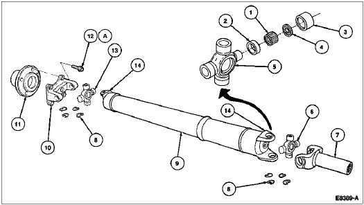
The driveshaft is a tubular shaft used to transfer engine torque from the transmission output shaft (7060) to the differential in the rear axle housing (4010), which in turn transmits torque through the halfshafts to the drive wheels.
The driveshaft assembly consists of the following components:
- two single cardan rear axle shaft universal joints (4249)
- a driveshaft slip yoke (4841)
- a welded aluminum tube assembly.
- driveshaft centering socket yoke
The driveshaft slip yoke permits the driveshaft to move forward and rearward on the transmission output shaft during drivetrain movement and during driveshaft removal and installation.
Driveshaft Assembly—Disassembled View 
| Item | Part Number | Description |
|---|---|---|
| 1 | — | Needle Rollers (Part of 4635) |
| 2 | — | Grease Seal (Part of 4635) |
| 3 | — | Bearing Cup (Part of 4635) |
| 4 | — | Thrust Washer (Part of 4635) |
| 5 | — | Spider (Part of 4635) |
| 6 | 4635 | Universal Joint |
| 7 | 4841 | Driveshaft Slip Yoke |
| 8 | — | Snap Ring (8 Req'd) (Part of 4635) |
| 9 | 4602 | Driveshaft |
| 10 | 4782 | Driveshaft Centering Socket Yoke |
| 11 | 4851 | Rear Axle Universal Joint Flange |
| 12 | N800574-S160 | Bolt (4 Req'd) |
| 13 | 4635 | Universal Joint |
| 14 | — | End Yoke (Part of 4602) |
| A | — | Tighten to 95-130 Nm (71-95 Lb-Ft) |
Driveshaft, Rear
One Piece
Removal
-
Drain fuel tank (9002).
-
Raise vehicle on a frame contact hoist.
-
Remove crossmember on forward side of fuel tank.

-
Remove muffler outlet pipe (5255) at muffler (5230).

-
Lower muffler outlet pipe and support with wire.

-
Remove exhaust outlet pipe frame bracket (5260) from exhaust pipe hanger stud.

-
Support mufflers and remove exhaust outlet pipe frame brackets from rear frame rails, lower exhaust system and remove complete system from vehicle.

-
Remove fuel tank filler pipe retaining bolt from RH frame rail.

-
 CAUTION: Use care not to damage fuel tank.
 Place a transmission jack under fuel tank.

-
Remove fuel tank support (9053) on forward side of fuel tank.

-
Remove sub-frame center support member (5K065) at rear of fuel tank.
-
Remove fuel tank support straps (9092). Lower fuel tank approximately 15 cm (6 inches).

-
NOTE: If original mark is not visible on rear axle universal joint flange (4851), mark both the rear axle universal joint flange and driveshaft centering socket yoke (4782).
Locate original paint mark on rear axle universal joint flange and mark driveshaft centering socket yoke in same location.

-
Remove four driveshaft retaining bolts.

-
Separate the driveshaft (4602) from the rear axle universal joint flange. Pull the driveshaft toward the rear of the vehicle until the driveshaft slip yoke (4841) clears the extension housing (7A039) and oil seal (7052). Mark the slip yoke index in relation to the output shaft (7060) and remove driveshaft. Install a plug in the transmission extension housing to prevent lubricant leakage.

Installation
-
Lubricate the driveshaft slip yoke splines with Premium Long-Life Grease XG-1-C or K or equivalent meeting Ford specification ESA-M1C75-B. Remove the plug from the transmission extension. Inspect the housing seal for damage and replace if required. Align the slip yoke index mark with the mark on the output shaft.
-
NOTE: When installing a new driveshaft, align factory-made yellow paint mark at rear of driveshaft tube with factory-made yellow paint mark on outside diameter of driveshaft centering socket yoke.
Install the driveshaft. Do not allow the driveshaft slip yoke to bottom on the output shaft with excessive force.
-
Align marks on driveshaft centering socket yoke and rear axle universal joint flange. Install and tighten four retaining bolts to 95-130 Nm (70-95 lb-ft).

-
Raise fuel tank and install fuel tank support straps. Tighten retaining bolts to 29-41 Nm (21-30 lb-ft).

-
Install fuel tank filler pipe retaining bolt. Tighten retaining bolt to 2.7-3.7 Nm (24-32 lb-in).

-
Install sub-frame crossmember (5K068). Tighten the two retaining bolts to 20-30 Nm (15-22 lb-ft).

-
Install sub-frame center support member on forward side of fuel tank. Tighten bolts to 20-30 Nm (15-22 lb-ft).

-
Raise exhaust pipe and support with wire.

-
Support mufflers and install exhaust outlet pipe frame brackets to rear frame rails. Tighten retainer bolts to 17-23 Nm (13-16 lb-ft).

-
Install muffler outlet pipe to muffler. Tighten bolts to 28-40 Nm (21-29 lb-ft).

-
Install muffler outlet pipe hangers at rear axle housing (4010).

-
Install crossmember on forward side of fuel tank. Tighten bolts to 16-24 Nm (12-17 lb-ft).

-
Lower vehicle.
