PATS Diagnosis
Symptom Chart—Anti-Theft Warning—Perimeter
Refer to the Electrical and Vacuum Troubleshooting Manual for the connector numbers cited in the pinpoint tests.
| Condition | Possible Source | Action |
|---|---|---|
|
|
|
|
|
|
Steering Column/Ignition/Lighting Control (SCIL) Module Parameter Identification (PID) Index
| Display | Description | PID Content |
|---|---|---|
| CCNTSCI | Number of Continuous DTCs on SCIL | one count per bit |
| BOO_SCI | Brake Switch Input | ON OFF |
| PARK_BRK | Parking Brake Switch Input | ON OFF |
| TILT | Steering Column Tilt Switch | SHORT UP DOWN OFF |
| TELESCP | Steering Column Telescope Switch | SHORT IN OUT OFF |
| TILTPOS | Tilt Position Sensor | SENSED notSEN |
| TELEPOS | Telescope Position Sensor | SENSED notSEN |
| TURN_SW | Left and Right Turn Signal Switch | OFF LEFT RIGHT SHORT |
| LBEAMSW | Low Beam Switch | ON OFF |
| HBEAMSW | High Beam Switch | ON OFF |
| PARK_SW | Parking Switch | ON OFF |
| LIGHTSN | Ambient Light | DAY NIGHT |
| FLASH | Flash to Pass Switch | ON OFF |
| FTURN_L | Left and Right Front Turn Lamp | R_OPEN, L_OPEN, L/R_OPEN OK |
| RTURN_L | Left and Right Rear Turn Lamp | R_OPEN, L_OPEN, L/R_OPEN OK |
| TAILLMP | Left and Right Tail Lamp | OPEN OK |
| LOWBEAM | Low Beam Lamp | R_OPEN, L_OPEN, L/R_OPEN OK |
| AUTOLMP | Autolamp Switch | ON OFF |
| ALP_IMP | Autolamp Analog Input | 0-100% |
| DOMESW | Dome Lamp Switch | ACTIVE notACT |
| PANLDIM | Panel Dim Intensity Switch | 0-100% |
| HOOD_SW | Hood Ajar Switch | AJAR CLOSED |
| DECKLID | Decklid Ajar Switch | AJAR CLOSED |
| P_DR_SW | Passenger Door Ajar Switch | AJAR CLOSED |
| IGN_KEY | Ignition Key In/Out | IN OUT |
| IGN_SCI | Ignition Switch | START RUN OFF ACCSSY |
| WPPRKSW | Windshield Wiper Park Sense | notPRK PARKED |
| NUMKEYS | Number of Ignition Key Codes Supported | BCD (valid range 0-16) |
| DRLKCYL | Door Lock Cylinder | ON OFF |
| ENABLE | PATS System Status | ON OFF |
| FAILSAF | PATS System Status | ON OFF |
| Active Command | Display | Function |
|---|---|---|
| PID Latch | PID LATCH | ON OFF |
| One Touch Window Dwn & Accy Delay | ACCY RLY | ON OFF |
| Warning Lamps and Chime | CHIME | ON OFF |
| ANTI- THEFT | ON OFF | |
| AUTOLMP | ON OFF | |
| HIGH BEAM | ON OFF | |
| Illuminated Entry | INT LAMPS | ON OFF |
| MIRRORLAMP | ON OFF | |
| Decklid Release | RELEASE | ON OFF |
| Turn Signal and Marker Lamps | LF TURN | ON OFF |
| RF TURN | ON OFF | |
| LR TURN | ON OFF | |
| RR TURN | ON OFF | |
| PARK LAMPS | ON OFF | |
| Headlamp Control | LEFT LOW | ON OFF |
| RIGHT LOW | ON OFF | |
| HIGH BEAM | ON OFF | |
| DRUN LAMP | ON OFF | |
| LF CORNER | ON OFF | |
| RF CORNER | ON OFF | |
| Horn Control | HORN | ON OFF |
| Backlighting Intensity | INTENSITY | 0%-100% |
| Courtesy Lamp Intensity | INTENSITY | 0%-100% |
| Door Ajar Signal | DOOR AJAR | ON OFF |
| Transmit Signal Command | TRANSMIT | ON OFF |
| Brake System | BRK/SHIFT | ON OFF |
| PARK BRK | ON OFF | |
| Steering Column Control | TILT UP | ONE SECOND TIME OUT |
| TILT DOWN | ONE SECOND TIME OUT | |
| TELSCP IN | ONE SECOND TIME OUT | |
| TELSCPOUT | ONE SECOND TIME OUT | |
| Keycode Erase Time Set | MINUTES | 8-63 MINUTES |
PINPOINT TEST A: NO COMMUNICATION WITH STEERING COLUMN/IGNITION/LIGHTING (SCIL) CONTROL MODULE
| TEST CONDITIONS | TEST DETAILS/RESULTS/ACTIONS |
|---|---|
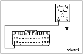
| A1 CHECK CIRCUIT 875 (BK/LB) FOR OPEN | |

Steering Column/Ignition/Lighting Control Module Connector C288 |
|
 |
Connect an ohmmeter between the steering column/ignition/lighting control module connector Pin C288-14, Circuit 875 (BK/LB) and ground.
|
GO to A2 .
NO SERVICE Circuit 875 (BK/LB) for an open. RESTORE the vehicle. REPEAT the Steering Column/Ignition/Lighting Control Module Self Test.
|
|
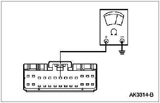
| A2 CHECK CIRCUIT 57 (BK) FOR AN OPEN | |

Steering Column/Ignition/Lighting Control Module Connector 287 |
|
 |
Connect an ohmmeter between the steering column/ignition/lighting control module connector Pin 287-7, Circuit 57 (BK) and ground.
|
GO to A3 .
NO SERVICE Circuit 57 (BK) for an open. RESTORE the vehicle. REPEAT the Steering Column/Ignition/Lighting Control Module Self Test.
|
|
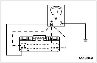
| A3 CHECK FOR B+ SUPPLY ON THE STEERING COLUMN/IGNITION/LIGHTING CONTROL MODULE CONNECTOR C287 | |
 |
Connect a voltmeter to each of the following steering column/ignition/lighting control module connector C287 Pins. Note the voltage reading at each Pin:
|
GO to Communication Network Diagnostics in Section 418-00 to diagnose the network concern. Contact us for a diagram.
NO For each suspect circuit, REFER to the Electrical Vacuum Troubleshooting Manual, Cell 58, Lighting Control Module and Cell 11, Circuit Protection/Fuse Panel to identify the subsystem in need of service. SERVICE as required. GO to A4 .
|
|
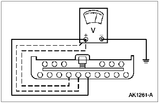
| A4 CHECK FOR B+ SUPPLY ON STEERING COLUMN/IGNITION/LIGHTING CONTROL MODULE CONNECTOR C289 | |

Steering Column/Ignition/Lighting Control Module Connector C289 |
|
 |
Connect a voltmeter to each of the following steering column/ignition/lighting control module connector C289 Pins. Note the voltage reading at each Pin:
|
GO to Communication Network Diagnostics in Section 418-00 to diagnose network concern. Contact us for a diagram.
NO For each suspected circuit, REFER to the Electrical Vacuum Troubleshooting Manual, Cell 58, Lighting Control Module and Cell 11, Circuit Protection/Fuse Panel to identify the subsystem in need of service. SERVICE as required. RESTORE the vehicle. REPEAT the steering column/ignition/lighting control module self test.
|
|
